Introductory Soil and Water Conservation Engineering
II Semester 3rd Feb to 30th June 2020, 2019-20
Teacher Information
Professor
|
Email
|
Phone
|
Dr. K. C. Shashidhar
|
shashidhar.kumbar@gmail.com
|
9448103268
|
Class-5 Reference Material
Gully classification and control measures
Gully Erosion
The gullies are linear incision channels of at least 0.3m width and 0.3m depth. Gully erosion creates either V- or U-shaped channels. Gullies are primarily formed by concentrated runoff converging towards lower points of the watershed. Thus, erosion occurring in these channels is known as concentrated flow erosion. Undulating fields cause runoff to concentrate in natural swales as runoff moves down slope in narrow paths in the form of channelized flow. A swale is a low tract of land, which is moist or marshy. It may be naturally occurring landscape or human-created. Continued gully erosion removes entire soil profiles in localized segments of the field. As gullies grow, more sediment is transported.Gully erosion is the advance stage of channel or rill erosion in which the size of rill is enlarged which cannot be smoothened by ordinary tillage implements. Process of gully formation follows sheet and rill erosion. Gully erosion produces channels larger than rills. These channels carry water during and immediately after rains.
Gullies may also be developed from rills which are unchecked. Development of gullies also takes place by ruts or tracks formed by the movement of machineries, down the slope.
The rate and extent of gully development are closely related to the amount and velocity of runoff water, since large amount of flowing water tends to detach and transport the soil in relatively larger amount. The amount of runoff water available is dependent upon the size and runoff producing characteristics of the drainage area (watershed) involved. The amount of sediment from gully erosion is usually less than from upland areas. In tropical areas, gully growth following deforestation and cultivation has led to severe problems from soil loss, and damage to building, roads and airport. The rate of gully erosion depends primarily on the runoff-producing characteristics of the watershed, the drainage area, soil characteristics, the alignment, size and shape of the gully, and the slope in the channel.
Ravine Erosion
A ravine is a very narrow, steep sided fissure in the Earth's surface. Ravines are smaller than valleys, but larger than gullies, although a ravine has the potential to develop into a valley, over the course of thousands of years. A ravine is generally a fluvial slope landform of relatively steep (cross-sectional) sides, of the order of twenty to seventy percent in gradient. Ravines may or may not have active streams flowing along the down slope channel which originally formed them. Moreover, often they are characterized by intermittent streams, since their geographic scale and their catchment areas may not be sufficiently large to support a perennial stream.

Ravine erosion. (Source: http://wiki.fis-ski.com/images/Ravines.jpg)
Typically, a ravine is formed through the process of erosion, and it starts out as the site of a small stream or river. Over time, the water wears a deep groove into the Earth, which attracts water as it drains from other locations, speeding up the erosion process. Eventually, a ravine may lose its stream, or have only intermittent water flow, because of lack of water supply from the catchment. Sometimes, however, a ravine will have a year-round watercourse.
Generation of large quantities of waste water in the urban areas and a generally poor urban drainage promote the formation of ravines. It is common for water to collect in a large mass in urban areas, creating a torrent, because it cannot percolate naturally through the soil to drain away. Because the water eventually finds a path to flow under gravity, it can end up creating a cutting in periods of flooding and heavy rain, and this will develop into a ravine.
Ravines have historically been used for garbage disposal, because of their depth and steep sides. Although this practice is largely discouraged today, ravines still tend to collect garbage, which is carried by the water which periodically pours through them as well as being tossed in by careless litterers. In urban areas, service organizations may designate a day each year to clean up local ravines, canyons, and waterways so that the garbage is not allowed to accumulate for too long.
Depending on the location of a ravine, it may also serve as habitat for local wildlife, especially in regions where wildlife is under pressure due to human habitation. Humans tend to avoid ravines, since they are difficult to navigate, and this allows a variety of creatures to move in and live undisturbed at the site. As a result, ravines are sometimes developed into habitations for birds and other forms of wildlife.
Stages of Gully Erosion
Stage1: In this stage channel erosion and deepening of the gully bed takes place. It is initiation stage and this stage normally proceeds slowly.
Stage 2: It is the development stage, in which due to runoff from upstream portion of the gully head, the size of gully width and depth is enlarged.
Stage 3: This is the healing stage, in which vegetation starts to grow in the channel. During this stage, there is no appreciable erosion in any form, from the gully section.
Stage 4: This is the last stage of gully development, in which gully is fully stabilized. No further development of gully occurs, unless healing process is disturbed. The channel has a stable gradient and gully walls gain a stable slope and vegetation begins to grow in abundance to cover the soil surface.
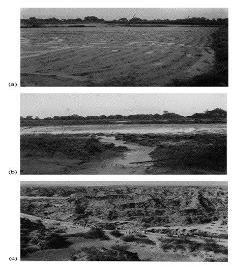
(a) Initial stage of land degradation, i.e. wash off erosion in cultivated field, depicting concentration of flow inducing incarnation of rill. (b) Runoff causing gully head cut at the point of vertical fall, beginning of severe land degradation. (c) Severely degraded ravine waste land in the Yamuna Chambal ravinous belt. (Source: http://www.sciencedirect.com/science/article/pii/S0378377402001580)
Classification of Gully: Gullies are classified as follows:
1) Based on Shape of the Gully: Gullies are classified into the following two shapes:
a) U-Shaped
Generally found in the alluvial plains, where surface and sub-surface soils are eaisly erodible. The specific features of these gullies are:
- U-shaped cross-section
- Longitudinal slope of gully bottom is usually parallel to the slope of the land, through which the gully passes.
- The runoff contributing catchment area being large, the discharge passing through these gullies is large.
- The velocity of flow is relatively lower than that of the V-shaped gullies.
- U-shaped gullies continue to grow headward.
- The lateral spacing of these gullies is large.
- Active erosion in these gullies, is from side banks and the gully head as a result of undercutting at these at the base of vertical cut.
- These gullies do not grow deeper, but becomes wider and longer, progressing headward
b) V-shaped
The V-shaped gullies are often developed where the sub-soils are tough enough to resist the rapid cutting of soil by the runoff. As resistance to erosion increases with depth, the width of cut decreases accordingly and results in development of V-shaped gully.
V-shaped gullies have the following major features:
- V-shaped cross-section.
- Generally, appear on sloping field.
- Longitudinal gradient of channel is greater than the land slope.
- Catchment area contributing the runoff is small.
- The lateral spacing between these gullies is small.
- Tha amount of discharge, passing through these gullies is small but has higher velocity.
- The V-gullies make the contour cutivation difficult.
- V-shaped gullies often devlop from rill erosion, when water is concentrated from several rills into one.
The shape of the gully depends upon the soil characteristics, climatic conditions, age of the gully and the types of erosion.
2) Based on State of the Gully
Gullies can be classified into the following types:
i. Active Gullies: active gullies are those, whose dimensions are enlarged with time. The size enlargement is based on the soil characteristics, land use and volume of runoff passing through the gully. The gullies found in plain area is active.
ii. Inactive Gullies: dimension do not appreciably change with time. These gullies found in rocky areas, are inactive because rocks are resistant to erosion by the runoff flow.
3) Based on Dimensions of Gully
Gullies are classified based on their size as:
i. Small Gullies, can be easily crossed by farm implements and can also be smoothened by ploughing and other land development operations and by stabilizing them through vegetation.
ii. Medium Gullies, cannot be easily crossed by farm implements. They can be controlled by terracing or ploughing operations. In medium gullies, the sides are stabilized by promoting vegetative growth on them.
iii. Large Gullies: these gullies cannot be reclaimed. For controlling these tree plantation is done as an effective measure.
Causes of Gully Erosion
There are two types of causes to activate the gully formation:
a) Natural Causes
- Rainfall
- Runoff
- Flood
- Soil Properties
- Vegetative Cover
b) Anthropogenic Causes
- Creating land surface without vegetation.
- Road construction
- Adoption of faulty tillage practices.
- Overgrazing and other form of biotic pressure on the vegetative cover, existing on the land surface.
- Absence of vegetative cover.
- Improper construction of water channels, roads, rail lines, cattle trails etc.
Effect of Gully Erosion
- Loss of soil productivity
- Adverse effect on other water resource facilities
- Loss of reservoir storage capacity
- Flood impacts
- Recreational impacts
- Deterioration of water quality
Introduction to Control Measures
Gullies are formed by excessive surface runoff, flowing with high velocity and force that are sufficient to detach soil particles and carry away them along the runoff flow path. Gully and channel erosion frequently occur because of increased water flowing from denuded areas. The runoff can start from bare land, faulty drainage, farm roads, neglected rills and furrow in farm field or from clogged drainage canals.
For controlling gully erosion, the following considerations are very important:
- Improving the catchment area of the gully
- Stabilization of gully head
- Safely conduct water through the gully, provided that it is not a part of natural drainage system of the area
- Adoption of gully control measures to stabilize themGully Control Measures
- Control by Vegetation: vegetation provides soil cover and protect the gully against scouring. It also reduces the flow velocity by increasing the hydraulic resistance of the channel section, thereby the scouring and ability of runoff is reduced to a great extent.
- Control by Structures: structures are used to control the flow velocity. Structures are of two types:
A) Temporary Structures: temporary structures are constructed to serve the following purposes:
- To collect sufficient amount of soil on their upstream portion to build up a huge growth of vegetative cover.
- To check the gully erosion until sufficient vegetation has been established at the critical points of gully.
Temporary Structures are:
1) Brushwood dam:
- Single row brushwood dam
- Double row brushwood dam
2) Loose rock fill dam
3) Log check dam
4) Netting dam
5) Staggered trenches or bunds
6) Terraces (there are stable permanent terraces also used for crop cultivation)
7) Grassed water ways
B) Permanent structures: These structures are made of permanent materials such as: masonry, reinforced concrete or earth etc.
For the purpose of gully control, the following types of permanent structures are used:
1) Spillway:
a) Drop inlet spillway
b) Straight drop spillway
c) Chute spillway
2) Rubble masonry dam
3) Concrete dam
4) Gabions
5) Silt trap dam
Temporary Control Structures
Temporary physical and structural measures such as gully reshaping, brushwood dam, protection by sandbag, loose stone barrier, gabion structures and arc-weir check-dams are used to dissipate the energy of runoff and to keep the gully stable. Check-dams are constructed across the gully bed to stop channel bed erosion. By reducing the original gradient of the gully channel, check-dams reduce the velocity and erosive power of runoff. Run-off during peak flow is conveyed safely by check-dams. The structures can be either temporary or permanent. The choice of the measures and extent of their use will depend on the amount of the runoff and the status of the gully; whether young and actively eroding or mature and stabilizing naturally. Good judgment is required in determining what measures to be used that are both economical as well as effective. Consideration should then be given to the ways of stabilizing the gully head, floor and sidewalls.
An effective sediment and erosion control plan should:
- Minimize clearing: use site fingerprinting, buffers and construction phasing.
- Prevent off-site runoff from flowing across bare soils: use perimeter dikes and diversions.
- Stabilize bare soils on the site: use erosion control mats, planting, retaining walls.
- Remove sediment from runoff before it leaves the site: use stabilized construction entrances/exits, silt fences, sediment traps, check dams.
- Plan soil disturbance activities for the dry season.
Check Dam
a) To maintain minimum water level in the forest areas so as to avoid any fire ignition on land surfaces.
b) To maintain high soil moisture levels so as to minimize fire in the forest areas from occurring and spreading especially during prolonged dry and hot season
c) To prevent over-drainage of the peat land which will lead to drying out of the organic materials causing carbon release as well as land subsidence.
d) To conserve as much water as possible during the post-monsoon season that would help to recharge ground water.
Classification of Check Dam
The check dams are classified as:
- (1) Temporary check dam(a) Brushwood dams(i) one row or single post brush wood dam(ii) Double row post brush wood dams.(b) Semi permanent dams(i) Loose rock dam(ii) Netting dam(iii) Log check dam(2) Permanent check dam(a) Drop Spillway(b) Drop inlet spillway(c) Chute spillwayDurability of Check DamCheck dams can be built using various types of materials such as earth, sand (loose or in bags), timber (sawn or log), stones/rocks (loose or stacked), or concrete (precast form). In selection of the most appropriate materials to be used as the main components of the check dam structure, designer should take into consideration the following factors:
- Size and dimensions of check dam
- Site conditions (e.g. waterlogged, depth of peats)
- Accessibility of site
- Availability of suitable materials locally
- Designed service life of the structure (short-term, medium term or long-term)
- Cost of construction
Temporary Check Dam
Temporary check-dams, which have a life-span of three to eight years, collect and hold soil and moisture in the bottom of the gully to give vegetation an opportunity to establish. Runoff control structures may be needed to be commissioned in the gully.
Gully Reshaping and Filling
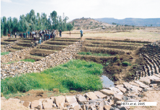
Gully wall reshaping involves cutting off steep slopes of active gully flanks into gentle slope (maximum at 45% slope), up to two-third of the total depth of the gully and construction of small trenches along contours for re-vegetating slanted part of the gully walls and beds. If the gully is wide and has meandering nature with huge accumulation of runoff flowing down; cut off soils and soil materials can be washed away by runoff water and requires construction of retaining walls to protect displaced (not yet stabilized) soils and soil materials and newly created sidewalls of the reshaped gully
.
Gully reshaping and filling. (Source: https://energypedia.info/images/a/aa/GullyReshapingRevegetation.png)

Gully wall reshaping without retention wall. (Source: http://www.bebuffered.com/downloads/ManualonGullyTreatment_TOTFinal_ENTRO_TBIWRDP.pdf)
Gullies with very little water flow can be stabilized by filling and shaping; that is, if the surface water is diverted, and livestock are kept out. Steep gully heads and gully banks should be shaped to a gentler slope (about a one-to-one slope). Filling of gullies is applicable only for small discontinuous gullies, in their early stages of development. The filled gully area can be planted and even be used for cultivation. Rills and incipient branch gullies may be filled in by spade, shovel or plough (on cultivated lands).
The practicability of shaping a gully depends on its size and the amount of fill needed to restore the gully to its desired shape. Steep gully sides can be reshaped. Topsoil should be stockpiled and re-spread over exposed areas to ensure the rapid establishment of vegetation. Annual grass and crops such Wheat, oats or barley can be used to provide a quick cover. It may be possible to temporarily divert water from the battered gully while grass is establishing.
The common practice of filling gullies with rubbish, logs, rocks, branches, twigs and other materials does very little to solve the problem. In most cases, particularly in gullies that carry copious runoff during the monsoon season, it makes the gully worse particularly if the placement and anchorage of those materials is not done properly.
Generally, in the filling and shaping process the following need to be considered: The common practice of filling gullies with rubbish, logs, rocks, branches, twigs and other materials does very little to solve the problem. In most cases, particularly in gullies that carry copious runoff during the monsoon season, it makes the gully worse particularly if the placement and anchorage of those materials is not done properly.
-
- The soil should be well compacted
- The filling operation should be done before the rains
- To protect it from erosion, close growing crops should be planted or seeded immediately
- The entire work of shaping and filling should be done in one operation
Brushwood Check Dam
Brushwood check-dams made up of posts and brushes are placed across the gully. The main objective of brushwood check-dams is to hold fine materials carried by flowing water in the gully. Small gully heads, no deeper than one meter, can also be stabilized by brushwood check dams. Brushwood check-dams are temporary structures and should not be used to treat ongoing problems such as concentrated run-off from roads or cultivated fields. They can be employed in connection with land use changes such as reforestation or improved range management until vegetative and slope treatment measures become effective.
The main requirement of temporary gully control structures is that, they must be quick and easy to construct, should be made by using cheap and readily available material in nearby areas.

Brushwood check dam. (Source: http://www.bebuffered.com/downloads/ManualonGullyTreatment_TOTFinal_ENTRO_TBIWRDP.pdf)

A single row brushwood check-dam front view. (Source: http://www.bebuffered.com/downloads/ManualonGullyTreatment_TOTFinal_ENTRO_TBIWRDP.pdf)
In areas where the soil in the gully is deep enough, brushwood check-dams can be used if proper construction is assured. The gradient of the gully channel may vary from 5 to 12 percent, but the gully catchment area should not be as such huge which produces high amount of runoff volume. There are two types of brushwood check-dams: these are single row and double row brush wood check-dams. The type chosen for a particular site depends on the amount and kind of brush available and on the rate and volume of runoff. The maximum height of the dam is one meter from the ground (effective height).
Single Row Brushwood Check-dams
These check-dams can be used where the rate of runoff is less than 0.5 m3/sec. The structure is temporary and its durability will depend on the quality of posts used. If possible live posts of willow, popular and other trees should be used (8-10 cm dia). Flexible branches are cut and woven around the posts. This dam is constructed across the channel or gully with the brush wood materials, laid along the flow of water, keeping the butt ends towards u/s face of the gully. The brushwood is kept in position by tying to the posts. Before the dam construction is begun, the sides of the gully or channel should be sloped to 1:1 and the gully bed should also be excavated for 15 cm depth along the entire gully width over which brushwood have to be laid. In addition, 15 cm excavation is also done into the bank to give necessary notch capacity. After excavation, the wooden posts of about 10 cm in diameter are driven in a line across the gully at an interval of 90 cm up to a depth of 75 cm in gully bed. The top of wooden posts should be kept at such a height so as to form a notch of required size. The brushwood is tied from the front line and the other lines are tied using galvanized wire for keeping them in position. The lowest layer of the brushwood must be the longest.

Vertical and side views of single row check-dam. (Source: http://www.bebuffered.com/downloads/ManualonGullyTreatment_TOTFinal_ENTRO_TBIWRDP.pdf)
This type of brushwood check-dam is suited where the rate of runoff is less than 1 m3/sec. The construction of the dam starts with an excavation in the floor and into the sides of the gully to a depth of 0.3-0.5 m. Two rows of posts, 5-10 cm in diameter and 1-2 m in length are placed into the holes, across the floor of the gully to a depth of 0.5-0.6 m. The spacing between the posts is 0.5 m. Brushwood or branches are packed between the posts. The height of the posts in the center should not exceed the height of the spillway otherwise the flow will be blocked and water may be forced to move to the gully sides.

Double row brush wood check-dam. (Source: http://www.bebuffered.com/downloads/ManualonGullyTreatment_TOTFinal_ENTRO_TBIWRDP.pdf)
Specifications for Brushwood Check-dams
- The choice for post brush check-dam must be made after careful examination of material availability in the near vicinity. Otherwise, problem of cutting all the sparse vegetation in the area would bring in undesirable results.
- Brush wood check-dams particularly single rowed ones can be strengthened with bamboo mat or sand filled bags on the upstream part to serve as a shock absorber and to dissipate the runoff energy during pick flows.
- Any tree or shrub species can be used as posts. But the wooden posts should be rot resistant and termite proof. The brushwood must not be very dry and easily breakable.
- To avoid the brushwood being removed by flowing water, it is necessary to fix the brushwood with rope, wire or nail.
- The ends of interlink materials should enter at least 30 cm into the sides of the gully.
- The space behind the brushwood check-dams must be filled with soil to the spillway, if either sand bag or bamboo mat is not used.
- If sprouting species (salix and popular) are selected as posts and interlink materials, brushwood check-dams should be constructed when the soil in the gully is saturated or during the early rainy season.
- If non-sprouting species are used as strips and interlink materials, brushwood check-dams can be constructed during any season
Loose Rock-fill Dam: This type of check dam is simple in construction and very effective for gully control. These dams are preferred in those areas, where plenty of loose rocks are available nearby the gully. The loose rock-fill dams are constructed with the help of stones. The stones are kept across gully width by wire netting made of fairly stout gauge of galvanized iron wire. The wire netting of about 2 meter or more in width is laid across the gully bed and over it the loose rocks are packed approximately up to half of the width of netting. The other half of netting is wrapped over the stones and laced to the other edge.

Making of loose stones check dam. (Source: http://www.geoengineer.org/multimedia-virtual/item/282-history-of-rockfill-dam-construction-part-2)
Design and construction specifications of loose stone check-dam
- The foundation of the dam is dug so that the length of the foundation will be more than the length of the spillway.
- The width of the foundation depends upon the reservoir level height.
- The dam should be properly keyed across its base and up the abutments to the crest elevation.
- An adequate spillway should be provided for safe disposal of water.
- An apron of non-erodible material should be provided at the base, to dissipate the energy of water falling through the spillway.
- Proper spacing between the successive dams should be ensured
- The height of the dam should be properly planned
- Stones should be placed such that they interlock easily and form a denser structure. If small stones are to be used they should be placed in the center and the outer surface covered with large stones to strengthen the dams.
- Loose stone check-dams can be strengthened by covering the upstream wall and the crest with bamboo/reed-mat.

A typical loose stone check-dam. (Source: http://opcgis.deq.state.ms.us/Erosion_Stormwater_Manual_2ndEd/Volume1/Chap_4_Sections/4_4/V1_Chap4_4_Runoff_Conveyance_CD.pdf)
Log Check-dam
When large size timbers are readily available in the nearby area of gully, the log check dams are used for checking the gully. In this dam, the logs are used as brushwood but they make the structures substantially stronger. In the log check dam, two rows of vertical wooden posts are formed by inserting the wooden posts in line with the gully bed and extending up to the sides above the flood level and then logs are packed between the two rows. The vertical posts should be at least 10 cm in diameter and 2 m long. The spacing should be kept about one meter between each row, with the two rows of posts half meter apart. In wide and shallow gullies, it is better to keep all vertical post to a height of 60 cm above the ground surface so that the top of the dam can follow the section of stream bed. If the gully has steep sides, it should have a rectangular notch in the centre but the notch must be large enough to pass whole of runoff. The vertical posts on either sides of notch are responsible for dissipating the kinetic energy of flowing water. Therefore logs should not be swept down by the flow, for which stout posts must be driven to a greater depth than the others. When the logs are fully packed between the rows of posts, the bottom layer to be sunk below the dam may be checked.

Log Check Dam. (Source: http://opcgis.deq.state.ms.us/Erosion_Stormwater_Manual_2ndEd/Volume1/Chap_4_Sections/4_4/V1_Chap4_4_Runoff_Conveyance_CD.pdf)
Netting Dam
In this dam wire netting is used to form a small check dam. The netting dams are usually located near the top end of the gullies. This dam consists of wooden posts which are driven into the gully bed to support a strip of wire netting and thus, forming a low wall across the gully. The height of dam is kept about 60 cm. The lower edge of the netting is buried into the gully bed. The brush or straw is also piled loosely towards upstream side of the netting wall to form a barrier, which is porous in nature. But it slows down the flow velocity and results in deposition of sediment on the upstream side.
Geo-Textiles for Gully/Erosion ControlGeotextiles are porous fabrics known in the construction industry as filter fabrics, road rugs, synthetic fabrics, construction fabrics, or simply fabrics. Geotextiles are manufactured by weaving or bonding fibers made from synthetic materials such as polypropylene, polyester, polyethylene, nylon, polyvinyl chloride, glass and various mixtures of these. The uses of geotextiles include separators, reinforcement, filtration and drainage, and erosion control.
Geotextiles can be used for erosion control by using it alone. Geotextiles, when used alone, can be used as matting. Matting's are used to stabilize the flow on channels and swales. Also, matting is used on recently planted slopes to protect seedlings until they become established. Also, matting may be used on tidal or stream banks where moving water is likely to wash out new plantings. Geotextiles are also used as separators.

Mulch geotextiles. (Source: http://coirgreen.wordpress.com/2013/04/03/coirgreen-geotextiles-an-effective-soil-erosion-prevention-method/)
Sandbag Check-Dam
Sandbag check-dams are made from used jute or polyethylene bags (50 kg) filled with soil/sand. The bags are piled up to a maximum of 3 – 4 layers to form a small check-dam. This cheap technique is particularly useful in areas with insufficient supply of stones for building ordinary check-dams. By erecting sandbag dam’s large rills or small gullies (finger gullies) can be controlled, while they are not suitable for the treatment of large gullies.

Sandbag check-dam. (Source: http://www.aquadam.net/Construction/Apple%20Creek-CA%20Dam/apple2.html)
Gravel-filled Burlap Bags
Gravel-filled burlap bags may be used for temporary check dams in areas of concentrated flow. The burlap bag flaps under the bags is folded in a direction away from the water flow. Gravel bag check dams are constructed such that the crest of the downstream check dam is approximately level with the toe of the upstream check dam. The check dams are installed so that the side end points are higher than the centerline crest. Erosion caused by high flows around the edges should be corrected immediately.
Retaining Wall with Bamboo-MatIn gully rehabilitation scheme, the difficult part is to control the lateral flows which are coming from farm fields, footpaths, degraded grazing areas and other miscellaneous land use types. To protect the lateral flows and hence mass movement and soil sliding/melting from fragile sidewalls of a gully, retaining walls made out of reed/bamboo mat can be installed along the foot of the sidewall. The mat can be strengthened on the lower side by wooden sticks, possibly using vegetative propagating species like popular, willow and indigenous species. "Mini" bundles, with or without pegging, are also employed in small soil and moisture pockets. Arundo donax and Hyparrhenia stems consisting of three to four nodes each proved particularly useful for this purpose. Retaining, bundling and pegging commence with the onset of the rainy season.

Protecting gully sidewall using bamboo-mat retaining wall. (Source: http://www.bebuffered.com/downloads/ManualonGullyTreatment_TOTFinal_ENTRO_TBIWRDP.pdf)
Precast Concrete Stacked Blocks Check-Dam
Stacked precast concrete blocks can also be used for the construction of check dam structures. Some requirements for precast concrete block check dams are:-
- Proper foundation has to be provided to prevent excessive deformation and bearing capacity failure. If necessary the layer of soft and peat soils should be replaced.
- The stacked precast concrete blocks should be stable and designed as mass gravity wall that is able to resist both hydraulic and earth pressures.
- The dimensions of each individual precast block are to be decided based on handling as well as stability requirements
- The precast blocks should be able to be removed swiftly in case of overtopping and flooding problems.

a) Side View

b) Upstream View
Precast Concrete Stacked Blocks Check Dam Structures. (Source: http://info.water.gov.my/attachments/article/324/GuidelineCheckDamsCompleteSet.pdf)
Locally Available "Organic" Gabion Boxes
“Organic” gabion boxes are made from locally available bamboo and reed strips, which are woven and tied together to form cubic, permeable boxes to be filled with stone. The organic gabions are placed across gully floors, and buttressed downstream for stability. The characteristic of the specific location determines the height and the width of the organic gabion check-dam, and consequently the number and size of gabions to be utilized for. Consequently, the velocity of the run-off is reduced, and sedimentation creates a favorable atmosphere/ environment for the establishment of permanent biological structures. Accordingly, appropriate vegetative structures are put in place so as to strengthen and finally replace the "organic" gabion that rots over time.

Check-dams constructed out of organic boxes (bamboo and reed mat). (Source: http://www.bebuffered.com/downloads/ManualonGullyTreatment_TOTFinal_ENTRO_TBIWRDP.pdf)
Silt Fence
A silt fence is a temporary sediment barrier consisting of fabric stretched across and attached to supporting posts and entrenched into the soil. It is generally installed perpendicular to the flow direction to slow down or stop water and to allow filter/perimeter protection, settling of soil particles, and/or reduce water velocity/erosive forces.

Silt Fence. (Source: http://www.interstatelandscaping.com/Page_4.html)
Sediment Basin
Semi-permanent to permanent version of the Sediment Trap is constructed by excavation, embankment, or a combination of these to intercept, trap, and retain sediment from runoff while allowing detained runoff to slowly drain, infiltrate, or both. These structures are used for indefinite periods of sediment collection associated with long term disturbance of the earth such as mining, farming, unpaved road drainage, etc. Sediment and runoff storage capacities are often larger than sediment traps, and embankments are usually constructed from more permanent materials such as compacted earth, rock, concrete, etc. Sediment laden runoff can be drained and filtered by perforated pipe, rock filtration, rock dam seepage, infiltration, pumping, or a combination of these.

Sediment Basin. (Source: http://www.al.nrcs.usda.gov/news/sstories/1109sed_basin_lee.html)
Permanent Structures
Spillway
Dams and barrages are constructed to store runoff water from the catchments for its simultaneous and/or subsequent use for hydro power generation, irrigation, drinking water supply, flood control, etc. They are much larger structures constructed across rivers and tributaries than what have been discussed so far as means of gully control measures.

Spillway in bhakra dam and spillway in hirakud dam. (Source: http://profskmazumder.com/IT%20PDF/Ref_02.pdf)
Components of a Spillway
A spillway generally has the following components
- Entrance channel
- Control structure
- Discharge channel (or waterway)
- Terminal structure (energy dissipater)
- Exit channel
However, entrance and exit channels may not be required for some spillways, which one usually comes across in agricultural lands.
1. Entrance Channel
Entrance channels are required in those types of spillways in which the control structure is away from the reservoir. The entrance channel draws water from the reservoir and carries it to the control structure. Entrance channels are not required for spillways which draw water directly from the reservoir.
2. Control Structure
The control structure (also called control) is the most important component of the spillway. It controls the outflow from the reservoir. The control structure is designed such that it does not permit the outflow from the reservoir when the water level is lower than a predetermined level but permits the outflow as soon as the water level rises above that level. Generally the control structure is located at the upstream end of the spillway structure. The control structure usually consists of either an orifice or a weir. In most of the spillways, the control structure is an overflow crest of a weir. The weir may be sharp-crested, board-crested or ogee-shaped.
3. Discharge Channel (or waterway)
The outflow released through the control structure is usually conveyed to the terminal structure through a discharge channel or waterway. Thus the discharge channel conveys the water safely from the control structure to the river downstream. It is also called a conveyance structure. The conveyance structure may have different forms. It is usually the downstream face of an overflow darn for the spillway constructed as an overflow spillway in the body of the dam. It may be in the form of an open channel, a closed conduit placed through or under a dam, or a tunnel excavated through an abutment, depending upon the type of spillway. The discharge channel may have a variety of cross-sections, depending upon the geologic and topographic characteristics of the site and the hydraulic requirements.
4. Terminal Structure (energy dissipater)
When the water flows from the reservoir over the spillway, the static energy is converted into the kinetic energy. This results in very high velocity of flow at the downstream end of the spillway. It may cause serious scour at the downstream end. It may also damage the dam, the spillway and other appurtenant structures. It is, therefore, necessary that the high energy of flow is dissipated before the flow is returned to the river downstream. Terminal structures (or energy dissipaters) are provided at the downstream end of the discharge channel to dissipate the excess energy.
Hydraulic jump basin, a roller bucket, a ski-jump bucket, or some other suitable energy dissipating device is provided for the dissipation of excess energy. Smaller version of such energy dissipaters are also used with check dams and similar small structures.
5. Exit Channel
The exit channels are provided to convey the spillway discharge from the terminal structure to the river downstream. An exit channel is not required for the spillways which discharge water directly into the river downstream.
Classification of Spillways
The spillways can be classified into different types based on the various criteria, as explained below:
A. Classification Based on Purpose
- Main (or service) spillway
- Auxiliary spillway
- Emergency spillway
B. Classification Based on Control
- Controlled (or gated) spillway
- Uncontrolled (or ungated) spillway
- Free overfall (or straight drop) spillway
- Overflow or Ogee spillway
- Chute (or open channel or trough) spillway
- Side-channel spillway
- Shaft (or morning glory) spillway
- Siphon spillway
Classification Based on Purpose
a. Main (or service) Spillway
A main (or service) spillway is the spillway designed to pass a prefixed or the design flood. This spillway is necessary for all dams and in most of the dams, it is the only spillway. Therefore, in general terms, the spillway means the main spillway.
b. Auxiliary Spillway
An auxiliary spillway is usually constructed in conjunction with a main spillway. The main spillway is usually designed to pass floods which are likely to occur more frequently. When the floods exceed the designed capacity of the main spillway, the auxiliary spillway comes into operation and the total flood is passed by both the spillways.
c. Emergency Spillway
An emergency spillway is sometimes provided in addition to the main spillway. It comes into operation only during an emergency which may arise at any time during the life of the dam. Thus an emergency spillway is an additional safety valve of the dam. Some of the conditions which may lead to emergency are as follows:
(i) When the actual flood exceeds the design flood.
(ii) When there is an enforced shutdown of the outlets.
(iii) When there is malfunctioning of spillway gates.
(iv) When there is damage or failure of some part of the main spillway.
(v) When a high flood occurs before the previous flood has been evacuated by the main spillway.
The emergency spillway is generally in the form of a fuse plug or a breaching section which is washed out as soon as the water level in the reservoir reaches a predetermined elevation. The breaching section is sometimes called fuse plug spillway.
(i) An auxiliary spillway is designed to discharge a portion of design flood. An auxiliary spillway operates when the flood is less than the design flood but it is more than the capacity of the main spillway; whereas an emergency spillway operates only when the design flood is exceeded.
(ii) An auxiliary spillway may be of any type, but the emergency spillway is usually a fuse plug.
(iii) An auxiliary spillway may also be designed to work as an emergency spillway when the design flood is exceeded. It works as an auxiliary spillway when the flood exceeds the capacity of the main spillway but it is less than the design flood.
Classification Based on Control
a. Controlled (or gated) Spillway
A controlled spillway is one which is provided with the gates over the crest to control the outflow from the reservoir. In the controlled spillway, the full reservoir level (F.R.L.) of the reservoir usually coincides with the top level of the gates. Thus the water can be stored up to the top level of the gates. The outflow from the reservoir can be varied by lifting the gates to different elevations. It may be noted that in a controlled spillway the water can be released from the reservoir even when the water level is below the full reservoir level. Depending on the flow release requirement, some selected gates may also be opened.
b. Uncontrolled (or ungated) Spillway
The gates are not provided over the crest to control the outflow from the reservoir. The full reservoir level (F.R.L.) is at the crest level of the spillway. The water escapes automatically when the water level rises above the crest level. Thus, the main advantage of an uncontrolled spillway is that it does not require the gates, the operator and lifting power of the operator to operate the gates.
Classification Based on the Pertinent Feature
There are 8 different types of spillways based on the pertinent feature.
(1) Over-fall Spillway
A free over-fall spillway (or a straight drop spillway) is the one in which the control structure consists of a low-height, narrow-crested weir and the downstream face is vertical or nearly vertical so that the water falls freely more or less vertical. The overflowing water may discharge as a free nappe, as in the case of a sharp-crested weir, or it may be supported along the narrow section of the crest.Sometimes, the crest of the spillway is extended in the form of an overhanging lip for directing the discharge away from the downstream face. In all cases, the nappe is properly ventilated to prevent pulsating and fluctuating jets. If the tail water depth is adequate, a hydraulic jump may be formed after the jet falls from the crest, which can be used for the dissipation of energy. However, a long flat apron would be required to contain the hydraulic jump. Moreover, the floor blocks and an end sill may also be required for the establishment of the jump. A free over-fall spillway is commonly used for a low arch dam whose downstream face is almost vertical. This type of spillway is also used as a separate structure for low earth dams. The design of a free over-fall spillway is similar to that of a vertical drop weir.

(2) Ogee - Shaped (or Overflow) Spillway
An overflow spillway, can be gated or ungated, and it normally provides for flow over a gravity dam section. The flow remains in contact with the spillways surface (except for possible aeration ramps) from the crest of the dam to the vicinity of its base. The ogee or overflow spillway is the most common type of spillway. It has a control weir that is ogee or S-shaped. It is a gravity structure requiring sound foundation and is preferably located in the main river channel, although there are many spillways located on the flanks in excavated channels due to foundation problems.
The structure divides naturally into three zones:
(a) The crest,
(b) The Rear Slope
(c) The Spillway Toe

3. Chute (or open channel or trough) spillway
A discharge channel downstream of the control structure, known as a chute, may be straight or curved with sides parallel, converging, or diverging. It may be either rectangular or trapezoidal in cross-section and may have either a constant or a variable bottom width. Discharge channel dimensions are governed primarily by hydraulic requirements but the selection of profile, cross-sectional shape, width, and length is influenced by geological and topographical features at the site. Open channels excavated in the abutment usually follow the ground surface profile.
For earth dams and rockfill dams, a separate spillway is generally constructed in a flank or a saddle away from the dam if a suitable site exists. Sometimes, even for a gravity dam, a separate spillway is required when the valley is narrow and an overflow spillway cannot be provided at the dam site. The chute spillway is generally most suitable for such conditions.

4. Side-Channel Spillway
A side-channel spillway can be gated or ungated and provides for flow into a chute or tunnel at right angles because the abutment topography is not favorable for a normal crest alignment. A side channel spillway combines an over-fall section with a channel parallel to it, which carries the spillway discharge away to a chute or a tunnel. The analysis of flow in a side channel spillway has undergone gradual refinement over the years. The simplest form of analysis is based on the law of conservation of linear momentum, assuming that the only force producing motion in the channel results from the fall of water surface in the direction of spillway axis. The energy of the flow falling down the crest is assumed to be dissipated through it intermingling with the channel flow and offers no assistance in moving the water.

5. Shaft (or Morning Glory) Spillway
A shaft (or morning glory) spillway consists of a large vertical funnel, with its top surface at the crest level of the spillway and its lower end connected to a vertical (or nearly vertical) shaft. The other end of the vertical shaft is connected to a horizontal (or nearly horizontal) conduit or tunnel, which extends through or round the dam and carries the water to the river downstream. When the water level rises above the crest level, it starts overflowing the crest and drops from the rim of the funnel into the vertical shaft and then flows in the horizontal conduit, which conveys it past the dam. The transition between the shaft and the horizontal conduit should be smooth to avoid cavitation. A shaft spillway is used at the sites where the conditions are not favorable for an overflow spillway or a chute spillway. It is generally considered undesirable to construct a spillway just adjacent to an earth dam. Therefore, an overflow spillway is ruled out if there is not an adequate space. If the topography of the site is also such that a chute spillway cannot be constructed, a shaft spillway may be considered as an alternative to a side channel spillway.

6. Siphon Spillway
The discharge over an overflow spillway is a function of the head measured over its crest. Enclosing the crest and making the resulting conduit flow full can substantially increase this effective head. The head on the spillway is then the difference in elevation between the reservoir surface and the spillway outlet. However, the flow near the crest of the spillway would then be under a negative pressure. In other words, the conduit becomes a siphon. All necessary precautions must be taken to ensure that the vacuum is maintained and that it does not become so excessive as to cause cavitation.

7. Conduit (or Tunnel) Spillway
Tunnel spillways, are used with embankment dams, where there is no suitable location for a chute spillway. A competent rock abutment is required. Tunnel spillways can be gated or ungated, depending on topographic and geologic constraints at the tunnel entrance. In some cases, gates may be required. A tunnel spillway generally consists of the following elements:
- entrance structure,
- inclined tunnel section,
- flat tunnel section, and
- flip-bucket

8. Orifice Spillway
An orifice spillway is normally gated and is used when substantial discharge capacity is needed at low reservoir levels, as illustrated in Fig. 30.10. For instance, it is useful when sediment sluicing is required. It also is useful for diverting flow during construction. Gate sizes are normally smaller for these spillways, but higher head and sealing details can make them expensive.

Concrete Dam
A concrete dam is a structure designed and built for the purpose of holding back water and is constructed across the path of a river or a stream. Dams are built for a variety of reasons, including flood control, power generation, drinking water supply, irrigation, etc. A concrete dam is the strongest type of dam built in modern times and may take several forms. Concrete itself is a building material made from water, cement, sand and gravel, or aggregate. Dams constructed using concrete have three basic designs. An arch dam is a curved, relatively thin curtain of concrete, with the concave side of the curve facing downstream. This type of dam is made of solid concrete that is reinforced with steel. It relies on the pressure of the water behind it to add strength as the components of the resulting force push the sides of the dam into the walls on either side. Arch dams are particularly well suited for areas where a river flows at the bottom of steep canyons or gorges with solid rock at the banks. Some of the important dams in India are Bhakra (Punjab), Idduki (Kerala), Sardar Sarovar (Gujarat), Almaty (Karnataka), etc.
A gravity dam, as shown in fig. 31.1, is a type of dam that relies on its own mass to keep it stable and to hold back water. Gravity dams are often massive structures. The dam is made of concrete, but the main portion of its interior has core fill of rock rather than solid concrete. A gravity dam is usually not curved, and a cross section will resemble a right triangle, with the right angle at the bottom on the side facing the water and the side facing away from the water sloping downward so that the dam is thicker at the bottom. Gravity dams are better for areas where there is no firm bedrock or canyon walls for anchorage.
The third main type of concrete dam is the arch-gravity dam, which combines the features of both the arch dam and the gravity dam. Arch-gravity dams are curved dams that use the principle of the arch to bolster their strength but are much thicker than a typical arch dam and have a core of fill. They are designed so that their massive weight, combined with the increased strength of an arch over a straight-line structure, will keep the dam in place and hold back the water

Bhakra Dam, a concrete dam in the India. (Source: http://www.realtyfact.com/bhakra-dam/)
Flood Dam
A flood dam, operates as part of a flood control system to protect communities from uncontrolled flood waters. Such dams do not create reservoirs to store water for use in the future, nor do they generate hydroelectric power. They can be installed by government agencies and communities, and are subjected to regulation for safety. A flood dam needs to meet building guidelines and regulators can inspect it periodically to confirm if it is in good working order. In heavy rains, or when runoff from upstream becomes heavier than usual, the flood dam action starts. It retains water and controls its release to slowly allow levels of lakes and rivers to stabilize. In addition to protecting communities from flood waters, this measure also limits topsoil loss and other environmental problems that can occur in severe flooding. When conditions return to normal, the flood control dams can go back into a dormant mode.
Construction of large dams requires certain favorable site characteristics, such as a solid (rock) subbase, strong and stable (rock) sides, narrow section of the river, relatively steeper river gradient, no dominant seismic hazard in the region (however, dams are designed and constructed even in high seismic regions by design modifications), etc. Everywhere such specific site characters are not found. Hence, the sites for high dam construction are limited. High dams constructed in flatter terrain involve large area inundation that displaces people causing misery to them. Stopping of the natural flow of a river, re-habitation and resettlement issues for the displaced persons, loss of forest land, methane production from the vegetation submerged under the reservoir water, are some of the major environmental issues and concerns in India these days.

Gabions
Gabion walls are flexible structures where the design is based on the mass of the gabions providing stability against the over turning forces due to the soil and surcharges.

Types of Gabion Structures
(a) Box-Shaped Gabion
Gabion box-shaped structure is the most popular type of gabions of universal application. This means that if you wish, you can leave all attempts to optimize the design and just use the box-shaped gabions of most appropriate size. They have a classic structure - rectangular wire mesh filled with stones and can be used for the construction of retaining walls, building mounds and banks, or for landscaping.

Gabions box-Large (Jumbo Gabions)
When it comes to fast large-area coverage, we recommend the use of Jumbo - increased gabion structures, which can reach a length to 6 meters. This allows saving time for example, when installing a retaining wall or terrace, where the decisive importance is the length of the object. Such gabion structures could save you money, at least in the installation.
(b) Reno Mattresses
Reno Mattresses is another type of box gabion structures, which differs from other gabions in length and height. The principle of the device of this type of gabions is that it often has a height of only a few centimeters and is used when one wants to quickly cover a large area and do not lift it, but just strengthen it.
(c) Sack Gabions
Gabion structures in the form are recommended for the erection of towers. Of course, the usual box-shaped gabions are also suitable for this, but you cannot lose sight of the design idea for your project: perhaps it is based on rounded objects and the absence of any kind whatsoever angles.
Application
Roadway Protection, Retaining Walls, Rock fall Protection, Bridges and Culverts Protection, Coastline Structure and Protection, Channel Lining. Roadway Protection: The protection of highways and roads from environmental disasters are facilitated with the use of R gabions that stabilize the slopes protecting the shoulders.
Retaining Walls
Gabions used as retaining walls are functional, economical solution and a good alternative to other types of retaining structures due to their flexibility and permeability.

Rock Fall Protection
Rolls of fabric with lacing, done by joining together, are provided as a blanket to cover the surface of the slopes to protect any infrastructure built on the foot of the slopes against rock fall. Gabion constructed as retaining wall is an alternative.

Bridges and Culverts Protection
Bridge abutments and culverts are potentially at risk of scouring during heavy rains and strong flow of water. Gabion boxes and mattresses can be used as abutments and protective structure that aid the flow of water avoiding the danger of erosion due to their good permeability characteristics.
Coastline Structure and Protection
Gabions and mattresses are highly resistant to corrosion and other environmental effects which are suitable for marine works such as: retaining walls, ramps, beach protection, small jetties, groins, and piers built at great speed and minimum cost. The use of gabions and mattresses dissipate wave energy conserving beaches from being eroded.
Channel Lining
Channels are protected using gabion and mattress structures against erosion which control and guide the movement of water naturally.
Boundary or Security Fences
Units can be used as fences which are cost effective as compared to concrete fences.
Coffer Dam
It is an enclosure constructed around the construction site to exclude water so that the construction can be done in dry. A coffer dam is thus a temporary dam constructed for facilitating construction.

Concrete Arch Dam
Concrete arch dams are built in narrow, steep-walled canyons. The canyon walls take up the thrust exerted by the arch and the pressure of the water. Such dams can be extraordinarily thin. Vaiont Dam is 265 meters high, but only 22.7 meters thick at its base. In comparison, Hoover Dam is 221 meters high and 201 meters thick at its base and has a partial arch effect. In India, Idduki dam is known as Concrete arch dam, situated in Kerela.

Buttress Dam
Buttress Dams are made from concrete or masonry. The dam is supported at the downstream face by triangular shaped walls, called buttresses, at a suitable interval. They resist the force of the reservoir water trying to push the dam over. The buttress dam was developed from the idea of the gravity dam, except that it uses a lot less material due to clear spaces between the buttresses. Like gravity dams, they are suited to both narrow and wide valleys, and they must be constructed on sound rock, Fig. 31.9 shows buttress dam in Arizona.

Embankment Dam
Embankment dams are mainly made from natural materials. The two main types are earthfill dams and rockfill dams. Earthfill dams are made up of compacted earth, while rockfill dams are made up mainly from dumped and compacted rockfill. The materials are usually excavated or quarried from nearby sites, preferably within the reservoir basin.
A cross-section (or slice) through an embankment dam shows that it is shaped like a bank, or hill. Most embankment dams have a central section, called the core, made from impermeable material to stop water passing through the dam. Clayey soils, concrete or asphaltic concrete can be used for the core.


Embankment dam (Parambikulam dam, India). (Source: http://www.indianetzone.com/33/parambikulam_dam_kerala.htm)
Rubble Masonry Dam
These dams are used in gullies or stream channels with high rates of runoff or where vegetation cannot be established. The construction of this dam is recommended only, where rocks or stones are readily available in nearby areas. The minimum thickness of walls is kept as 30 cm. The downstream slope below the spillway is kept at least 1:2. The thickness of the base should not be less than 3/4th of the height of the dam.
Some details of rubble masonry dams are given as under:
- The minimum thickness of side walls cut off walls and apron should be about 30 cm.
- The thickness of main wall from the crest of spillway to the top of dam should not be less than 35 cm.
- To ensure proper settling, the upstream side of dam should be maintained at an angle of about 10o with the vertical.
- The length of apron should not be less than 1.5 times the height of dam, measured from apron floor to the spillway's crest.
- For drainage, the provision of drains or weep holes should also be made. They should be located near the base of dam.

- Sand Detention DamThe basic purpose of silt detention dam is to detain the silt load coming along the runoff from the catchment area into depressed part and simultaneously to harvest water. The location of such dam is decided at the lower reaches of the catchment where water enters the valley and finally made for taking out the water for irrigation purpose. For better result, a series of such dams can be constructed along the slope of catchment.Sand Detention Dam (Smoky canyon dam) (Source: http://www.delhur.com/projectTypes/waterResources.html)
 Rubber DamA symbol of sophistication, simple and efficient design, this most recent type of dam uses huge cylindrical shells made of special synthetic rubber and inflated by either compressed air or pressurized water. Rubber dams offer ease of construction, operation and commissioning in tight schedules. These can be deflated when pressure is released and hence, even the crest level can be controlled to some extent. Surplus waters would simply overflow the inflated shell. They need extreme care in design and erection and are limited to small projects. Example of Rubber type: Janjhavathi Rubber Dam (India).Janjhavathi Rubber Dam (India). (Source: http://www.thehinduimages.com/hindu/photoDetail.do?photoId=6452707)
 Steel DamA steel dam, consists of a steel framework, with a steel skin plate on its upstream face. Steel dams are generally of two types: (i) Direct-strutted, and (ii) Cantilever type. In direct strutted steel dams, the water pressure is transmitted directly to the foundation through inclined struts. In a cantilever type steel dam, there is a bend supporting the upper part of the deck, which is formed into a cantilever truss. This arrangement introduces a tensile force in the deck girder which can be taken care of by anchoring it into the foundation at the upstream toe. Hovey suggested that tension at the upstream toe may be reduced by flattening the slopes of the lower struts in the bent. However, it would require heavier sections for struts. Another alternative to reduce tension is to frame together the entire bent rigidly so that the moment due to the weight of the water on the lower part of the deck is utilized to offset the moment induced in the cantilever. This arrangement would, however, require bracing and this will increase the cost. These are quite costly and are subjected to corrosion. These dams are almost obsolete. Steel dams are sometimes used as temporary coffer dams during the construction of the permanent one. Steel coffer dams are supplemented with timber or earthfill on the inner side to make them water tight. The area between the coffer dams is dewatered so that the construction may be done in dry for the permanent dam. Examples of Steel Dam: Redridge Steel Dam (USA) and Ashfork-Bainbridge Steel Dam (USA).Redridge Steel Dam. (Source:http://commons.wikimedia.org/wiki/File:Redridge_Steel_Dam_UpstreamSide_GateControls_DSCN2191.JPG)
 Diversion DamA diversion dam is constructed for the purpose of diverting water of the river into an off-taking canal (or a conduit), which represent Indian dam. They provide sufficient pressure for pushing water into ditches, canals, or other conveyance systems. Such shorter dams are used for irrigation, and for diversion from a stream to a distant storage reservoir. It is usually of low height and has a small storage reservoir on its upstream. The diversion dam is a sort of storage weir which also diverts water and has a small storage. Sometimes, the terms weirs and diversion dams are used synonymously.Picture of Koyna Dam in Satara district, Maharashtra. (Source: http://www.thehindu.com/news/national/other-states/irrigation-water-diverted-for-industries-and-domestic-use-in-maharashtra/article4609969.ece)
 Storage DamThey are constructed to store water during the rainy season when there is a large flow in the river. Many small dams impound the spring runoff for later use in dry summers. Storage dams may also provide water supply, or improved habitat for fish and wildlife. They may store water for hydroelectric power generation, irrigation or for a flood control project. Storage dams are the most common type of dams and in general the dam means a storage dam unless qualified otherwise.

Tehri dam of India. (Source: http://www.indiamike.com/india-images/pictures/tehri-dam)
Timber DamMain load-carrying structural elements of timber dam are made of wood, primarily coniferous varieties such as pine and fir. Timber dams are made for small heads (2-4 m or, rarely, 4-8 m) and usually have sluices; according to the design of the apron they are divided into pile, crib, pile-crib, and buttressed dams. The openings of timber dams are restricted by abutments. When the sluice is very long, it is divided into several openings by intermediate supports: piers, buttresses, and posts. The openings are covered by wooden shields, usually several in a row one above the other. Simple hoists—permanent or mobile winches—are used to raise and lower the shields.Timber Dam. (Source: http://blog.thecivilengg.com/wpcontent/uploads/2011/09/timber-dam.jpg) Earth DamAn earth dam is made of earth (or soil) built up by compacting successive layers of earth, using the most impervious materials to form a core and placing more permeable substances on the upstream and downstream sides. A facing of crushed stone prevents erosion by wind or rain, and an ample spillway, usually of concrete, protects against catastrophic washout should the water overtop the dam. Earth dam resists the forces exerted upon it mainly due to shear strength of the soil. Although the weight of the structure also helps in resisting the forces, the structural behavior of an earth dam is entirely different from that of a gravity dam. The earth dams are usually built in wide valleys having flat slopes at flanks (abutments).The foundation requirements are less stringent than those of gravity dams, and hence they can be built at the sites where the foundations are less strong. They can be built on all types of foundations. However, the height of the dam will depend upon the strength of the foundation material.
Examples of earth-fill dam: The Banasura Sagar dam, which is the largest earthen dam in India and the second largest in Asia, impounds the waters of the Karamanathodu, a tributary of the Kabini river.The Banasura Sagar dam. (Source: http://www.banasura.com/banasura-sagar-dam)


In velocity calculation of the graded bund how can the slope is 0.05
ReplyDeleteHow casinos in and around India are exploiting online - KRFIR
ReplyDeleteIndian casinos use software 007카지노사이트 developed and sold by online gambling sites. Since many Indian 우리카지노가입 casinos use software from RTG, operators have partnered
If you’ve mastered a poker face and you’ve obtained the cash to ante up at the desk, you might have higher success at poker than playing in} other casino video games. Just like any other casino game, slots supply a risk to win actual cash. No one can assure you wins outcome of|as a outcome of} slots are a game of likelihood, however have the ability to|you presumably can} definitely get an higher hand when you use the profitable slot suggestions from this text. Due 로스트아크 to the immense recognition of on-line slot video games, the slot growth trade has seen plenty of new businesses. So, this text will element the step-by-step means of slot game growth. Also, to add some background, the article will answer necessary questions about slot machine software program growth.
ReplyDeleteExperience the true essence of nature and luxury with the finest resorts in Wayanad, nestled amidst misty mountains and lush greenery. Enjoy a peaceful stay at premium resorts in Mananthavady, offering modern comfort with traditional charm. Whether you’re looking for the best resort in Wayanad for a relaxing escape or planning a fun-filled vacation, Wayanad resorts for family provide everything you need. Couples can unwind at a serene Wayanad resort for couples, surrounded by breathtaking views. For a private and exclusive experience, choose a Wayanad resort with private pool or explore elegant luxury resorts in Wayanad that redefine comfort. Stay in beautifully designed cottages in Wayanad, or indulge in a luxury villa in Wayanad offering privacy, elegance, and modern amenities. For the ultimate getaway, book a luxury villa with swimming pool and create unforgettable memories in the heart of Wayanad’s natural paradise.
ReplyDeleteResorts in mananthavady
Discover the perfect Wayanad resort for couples, where romance meets nature in a serene hillside setting. Enjoy cozy evenings and breathtaking views surrounded by misty forests. Stay in charming cottages in Wayanad, designed to offer peace, privacy, and comfort for your dream getaway. For a touch of elegance, experience a luxury villa in Wayanad, where modern amenities blend seamlessly with natural beauty. Indulge in the ultimate relaxation at a luxury villa with swimming pool, where you can unwind in style and create unforgettable memories amidst Wayanad’s tranquil landscape.
ReplyDeleteResorts in Wayanad
Clouds View Nature Resort offers a serene escape in Wayanad with options like cottages in Wayanad, elegant stays for couples, and premium comforts that make it one of the top luxury resorts in Wayanad. Whether you prefer a Wayanad resort with private pool, a peaceful luxury villa in Wayanad, or a luxury villa with swimming pool, the resort provides a relaxing getaway surrounded by nature.
ReplyDeleteWayanad resorts for family
Escape to Clouds View Nature Resort, a perfect retreat in the hills of Wayanad. Enjoy cozy cottages in Wayanad, ideal stays for couples, and all the comforts of a luxury resort in Wayanad. Whether you seek a Wayanad resort with private pool or a peaceful luxury villa in Wayanad, the resort offers elegant luxury villas with swimming pool for a memorable stay amid nature.
ReplyDeleteBest resort in wayanad